Monday, 22nd May, 2017.
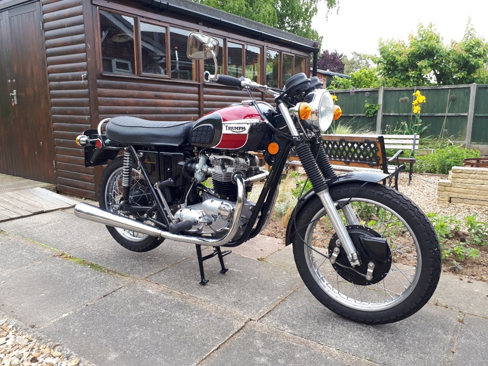
I've had a spot of bother with Daisy... (Yes, that's what I've called her!) Along with my other bikes, she was taken off the road over the last winter. On her first run out of this year, I only got a couple of miles down the road and she stopped... dead!. No messing about, no miss-firing, no running on one cylinder... just nothing. I pulled over and coasted to a standstill. I couldn't see anything wrong. There were no blown fuses, no wires fallen off, plenty of petrol, all the lights and instruments were working. I kicked it over... she fired up and ran!. To cut a long story a bit shorter, it happened again... and again! I eventually got her home on the back of a pick-up truck from the Two Wheel Centre. Very embarrassing! As everything else was working, it had to be the ignition system. After a lengthy e-mail 'conversation' with Paul Crowe in America and numerous test suggested by him, he reluctantly agreed that it had to be the C5 module that was at fault. 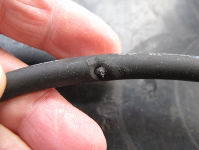 To buy a replacement C5 system was not financially viable at this time so I made the decision to strip it off and replace it with a 'Pazon Sure-Fire' system, the same as the one I'd successfully fitted to the Tiger 90. That meant doing a serious amount of re-wiring and today that task was completed. Daisy fired up immediately so we went for a ride... a 60 mile circular route north up the A1, west on the A421 and south back home on the A6. Daisy ran beautifully and never missed a beat. That was the end of the story but I missed a bit out in the middle.
Having stripped off the C5 and installed the Pazon, I was fitting a new set of HT plug leads. That was when I found the real cause of Daisy's woes. It wasn't the C5 system at all and I'd probably just replaced a perfectly good ignition system. The employee at the Triumph factory in 1971 who welded up the frame, didn't do a very good job of it. He'd left a short length, about 3/32", of welding wire stuck to the frame just where the HT lead ran. I only found it by accident when I was fitting the new HT leads as I snagged my finger on it. I checked the old HT lead that I'd taken off and sure enough, there was a small area of damage that coincided precisely with the wire on the frame. Over the 18 moths that the bike had been running, that wire had worn through the HT lead insulation and was intermittently shorting the high spark plug voltage down to the frame and stopping the engine. Needless to say, that wire has now been ground off and the frame touched up with black paint. Ho hum....
That's not the only mishap that Daisy has suffered. She lives in a rented "lock-up" that she shares with my mate Les's bikes. There are currently 4 bikes plus a load of other stuff in there and it was while I was attempting to retrieve a portable generator from the back of the garage that I accidentally hit the Bonneville petrol tank with it. Not hard enough to dent it but it did knock a fair sized chunk of paint off. I'd had the T90 tinware painted by Ernie in Baldock, so I took the tank to him to be repainted for the second time.
Let's move on... Three and a half years!
It's now October 2021. The Moto Guzzi that I owned when this story began has long gone, to be replaced with a 1968 Triumph Tiger 90, a 1955 AJS Model 18S, a 1954 Matchless G3/LS, a 1956 Matchless G80CS and most recently a Honda VFR750FS-RC36. They all have their own stories related elsewhere on this web-site and need not concern us here. A lot of other stuff has happened since the last update, not the least of which is the fact that I've re-located 100 miles north-east and now live in rural Lincolnshire. I also have a reasonable workshop and no longer have to work in an open back garden.
With six bikes to ride, the Bonneville has only covered 3,500 miles since she was rebuilt. Most of that being ridden at "sensible speeds" and with a total lack of drama. She has been pretty much faultless... up until the last trip out. The second Covid-19 "lock-down" was due to start at midnight last Wednesday, so before that happened, a run down to the Strathmore Arms in St Paul's Walden to meet up with some friends was needed. On the way home, there were some very dark clouds on the horizon ahead so in order to get home before the rain arrived, I hit the A1 northbound a lot faster than I came down... in fact, a lot faster than I'd ridden her since before the rebuild. I was turning around 6,000 rpm in top gear. A mile or two at that speed and the high frequency vibration destroyed the H4 halogen headlight bulb. The little metal shield over the filaments broke off, shorted the connection inside the bulb and blew the fuse that protected the lighting circuit. I made it home with no lights and only just made it before it got too dark to see. The Bonnie will be going into the workshop in the next few days to have the headlight sorted. I can't have that happening again.
Early November, 2021
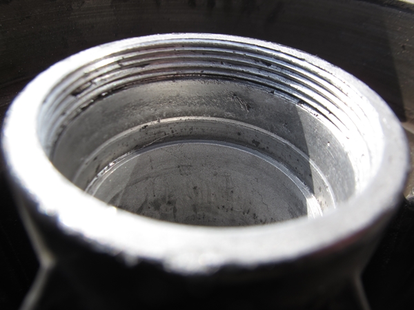
Daisy is now up on the bench in the workshop. I have an LED front headlight bulb to replace the halogen one that failed at high engine r.p.m. I've tried LED headlight bulbs in the past with limited success. Usually, it's a matter of focus... the LED arrays aren't in the correct place for the curved reflector to focus the light emitted into a coherent beam. Consequently, the light is scattered and not concentrated where it needs to be. However... it seems that things have improved and Paul Goff has supplied a new (and expensive) 12v LED bulb that he claims is the mutt's nuts. Time will tell.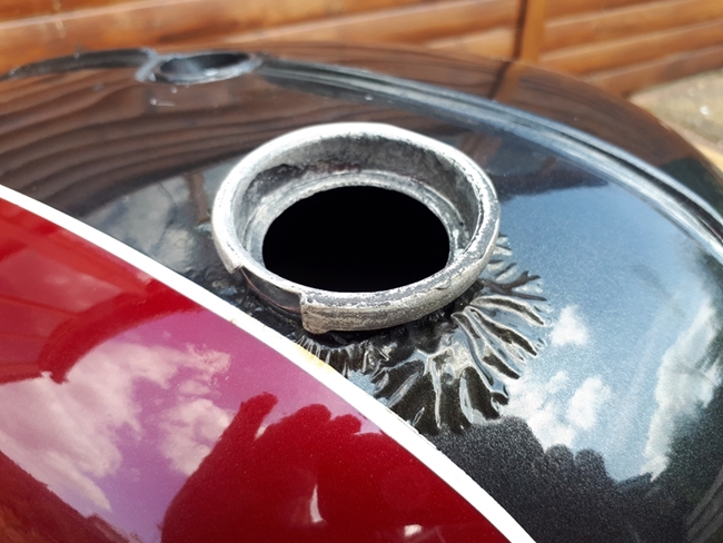 Yet another paint problem on the petrol tank. While Ernie made a terrific job on the tank when it was repainted a few years ago, the paint he used has bubbled up around the filler cap. I've suspected for a long time that this bike had been involved in an accident some time prior to me buying it. The damage to the primary chain case and air filter cover for one thing. Another indication is that the bike has a later set of front forks fitted. 1971 original forks didn't have polished aluminium sliders... they were introduced a couple of years later. I also believe that the petrol tank is an aftermarket replacement and not the original factory item. The filler neck is not welded into the tank body as it should be but is held in place by a rolled joint. I believe that this has allowed petrol vapour to seep out of the joint, under the paint, and cause the paint to bubble up and lift. While the bike is in the workshop, I'll get that sorted. I've run a layer of solder over the joint, inside the filler cap neck. That has secured the joint and will stop any further leaking of vapour or liquid from the joint. Now all I have to do is get the tank repainted... again!!
Since it was painted last, we've had the Covid-19 pandemic which has caused a lot of small companies to "go to the wall". Unfortunately, Ernie was one of them and he is no longer in the paint spraying business. I spoke to Nick at The Two Wheel Centre and he recommended "Dream Machine" in Nottingham, so I gave them a call. They would indeed paint my tank, so I took it across to them. When I got it back, a few weeks later it looked great. I was well pleased, but pleasure like that comes at a cost and at over £400, it wasn't the cheapest tank respray I've ever had!!
Monday, 7th February, 2022
I've finished the major service on the recently acquired Honda VFR750 and now, the Bonneville is back in the workshop... Not because there is a problem, but because I'm thinking about rebuilding the engine. I've run out of projects now, and I need something to keep me occupied or I'll end up watching daytime reality television... Not going to happen!! I would like to fit a 750cc "Big Bore" kit to boost the low end torque. Either the "Routt" kit or the offering from "Morgo". I will probably take the bottom end apart this time as I didn't do that before. The sludge trap will need cleaning and possibly a crank regrind as well. The crankshaft will need re-balancing with the larger pistons. I feel a trip to T & L Engineering coming on.
I would also like to re-instate the PowerArc C5 ignition system. I thought it was faulty and replaced it with the Pazon system. As mentioned above, the real cause of the problem was nothing to do with the C5. I've ordered some more Moroso HT cable from the States to replace the damaged lead. I will, of course, test it on the bench before making a final decision. Ho hum... watch this space!!
Wednesday, 23rd February, 2022. NOTE... Speedometer reading 3830.
 And so it begins... It's taken a little longer to get started than I anticipated as the Honda had to come back into the workshop for a niggling ignition problem. Hopefully, that is now sorted and today the bikes were swapped again. Just a few things to start... the frame, gearbox, chaincase and crankcase were all drained of oil. The handlebar mirror, petrol tank, seat and exhaust system were removed and put away for safe storage.
Thursday, 24th February, 2022
Carried on prepping the engine for removal. It's a heavy lump, so if I'm going to get it out by myself I need to remove as much stuff as I can while the engine is still in the frame. The footrests were the first to come off. Then the gearbox outer cover was taken off so that I could get to the oil pipes. On the other side of the engine, the clutch and primary drive have been stripped off. That's removed a few pounds that I won't have to lift out. I did have a bit of a problem getting the clutch hub off the gearbox mainshaft. It's on a keyed taper and I couldn't shift it. Then I had a "light bulb moment"... I had the correct Triumph service tool tucked away somewhere; I just needed to find it. It was found, of course, in a drawer labelled "Triumph Specific Tools". Stupidly, not the first place I looked!!. The extractor was screwed into the clutch hub and the centre bolt tightened. It took a lot of pressure before it came off with a bit of a bang. That cost me some knuckle skin but hey, that's the way it goes sometimes.
Sunsday, 27th February, 2022
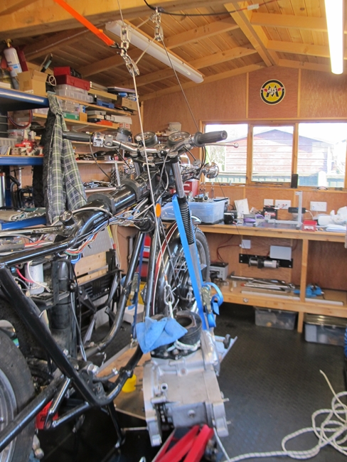
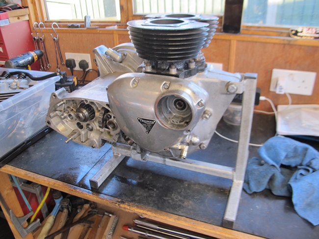 A little more progress has been made. The engine is now in its stand on the bench. I removed the rocker boxes and cylinder head head first but it was still a heavy old lump and at the moment, I have a damaged right knee so I was mindful that if I attempted to lift it out and my knee gave way under me, I would be sitting on the workshop floor with a 100lb of Triumph engine in my lap!! With that in mind, I rigged up the winch cable, through a couple of single sheaves and a travelling block on a short sling attached to some sky hooks screwed to the workshop roof beams. That provided a safety back up and would support the engine in a "worst case" scenario. I have a "cordless" remote control for the winch so I could let the cable out as needed. In the end, that was probably an over-kill but at least I didn't drop the engine. I did notice, however, that there was a noticeable amount of oil in the contact breaker cavity when I removed the Pazon ignition system. The oil seal is inexpensive, so that will be added to list of bits to buy.
Monday, 28th February, 2022
 First job today was to lift the barrels. The nuts were easy enough to undo, but it took a little persuasion to get the barrels separated from the crankcase. The bores and pistons look in good condition with no scoring. They would probably do someone a good turn if I don't use them myself. Particularly as they are still on STD and have never been re-bored. There is no detectable play in the big end bearings. I may get away without re-grinding the crank. I'll check them with a micrometer for any sign ovality. If I'm lucky, I may just need to replace the bearing shells.
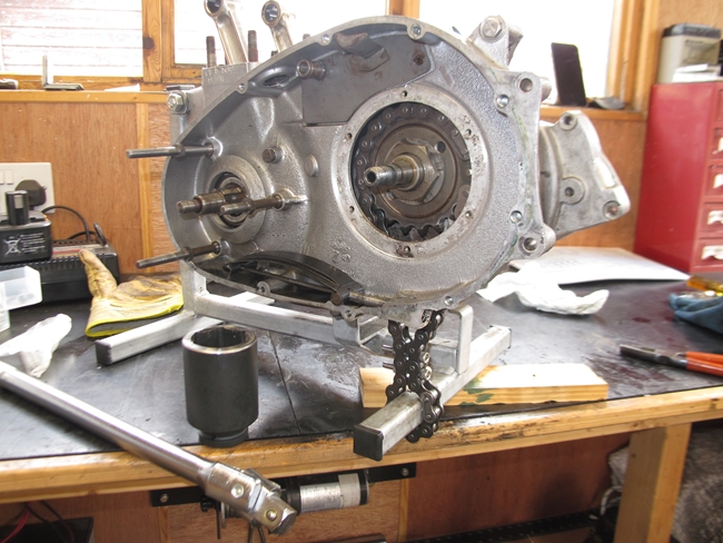
In preparation for taking the gearbox apart, and splitting the crankcase, it's necessary to remove the final drive sprocket. That's a 19 tooth sprocket which is going to be replaced with a 20 tooth one anyway. There is the problem, however of holding the sprocket to stop it rotating while I undo the nut. A method I've used successfully in the past is to use a short length of chain looped around the sprocket and the engine frame and secured with a couple of M6 bolts. That method worked well again today. The gearbox was put into top gear to effectively lock the mainshaft and output sleeve gear together. That way I could also undo the nut that holds the kickstart ratchet onto the other end of the mainshaft.
Wednesday, 2nd March, 2022
 Well... that didn't go as well as I'd hoped. I took the timing cover off, removed the idler pinion, and put the cover back on again. That way, the camshafts were no longer connected to the crankshaft. I put the C5 ignition module back into the timing cover and connected it up to the C5 coil, a couple of spark plugs, and a 12v battery. Using a cut down hex key in my cordless drill, I could spin in exhaust camshaft with the C5 encoder disc up to a couple of hundred rpm. The system worked fine and I got good sparks on the two plugs. So far, so good. I had hoped that I could replace the bulky C5 coil with two 6v Lucas coils wired in series in the same way that the Pazon ignition uses them. Unfortunately, that was a complete failure. No spark at all... bummer. So... that leaves me with a decision to make. Do I put the C5 system back on which will mean a fair bit of re-wiring or do I stay with the Pazon system that has worked perfectly for the last five years? I'll think on it for a bit!
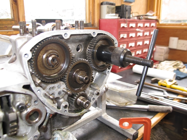
Having finished playing about with various ignition systems, there was some more 'mechanic-ing' to do. The timing pinions needed to be pulled off the two camshafts and the crankshaft. Fortunately, I have the Triumph service tools necessary to do just that and there was no drama.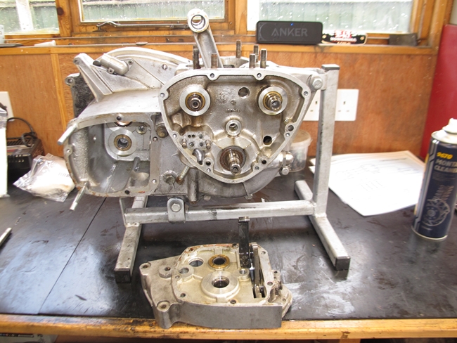 Next job... strip out the gearbox. That's a relatively easy task. The nut on the end of the mainshaft, I'd already taken off, along with all the parts that make up the kickstart ratchet. The nut and tab washer holding the gearbox sprocket were also already off. One 'Posidrive' screw, one hex socket cap screw, and one hex head screw to remove and the inner cover could be removed. It needed a little persuasion with a soft hammer to break the joint sealant and then it was pulled off. On preliminary inspection, all the internals look good. I'll replace the two ball bearings on the mainshaft, and the oil seal behind the sprocket as a matter of course. I'll probably replace the layshaft thrust washers as well. The layshaft needle roller bearings, I'll probably leave alone.
Sunday, 6th March, 2022
Forgive me for I have sinned. It's been a while since my last confession and right now I have to confess that I've spent way too many of our fine British Quids in the last few days. I'm now the proud owner of a "Morgo" 750cc conversion kit, a pair of "Lightening" billet aluminium connecting rods from Thunder Engineering, a pair of new E3134 camshafts manufactured by LF Harris and new "R" cam followers to match!! That little lot, and that's only the major bits, have hit my bank balance for well over a grand. I've also had a delivery from Grin Triumph Spares containing gaskets, oil seals and tab washers to replace those that I've removed during dismantling. And there will be more stuff to come.
Thursday, 10th March, 2022
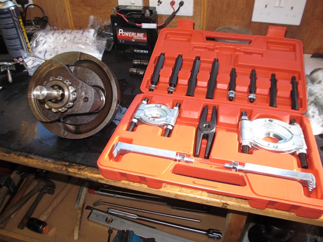 It certainly makes life easier when you have the right tools to do the job. The first task on the agenda was to remove the remaining bolts that were holding the two halves of the crankcase together. With the engine still being held in the bench stand, that was easy enough. With the last two being those that actually held the engine in the stand, the lump was now rolling around, unsupported, on the bench. According to the Triumph workshop manual, you need "Service Tool 61-6046", which I didn't have. It's simply a plate that mounts over the three studs that hold the alternator stator with a bolt in the middle to push against the end of the crankshaft. Easy enough to make, so I made one. It's not very pretty as my welding is abysmal, but it did the job and the two halves of the crankcase parted without any problem. The crankshaft pulled out of the timing side ball race with a little persuasion. The drive side roller bearing is in two parts. The outer ring remains in the crankcase while the caged rollers and the inner ring remain on the crankshaft. The inner ring and rollers needed to be removed for the crankshaft to be dynamically balanced at a later date. Fortunately, I had the gear to do that as well. The set of adjustable bearing removers being well up to the task. I needed to check the condition of the big-end bearing journals, and as I have new connecting rods anyway, the bearing caps on the old rods were undone, and the rods removed.
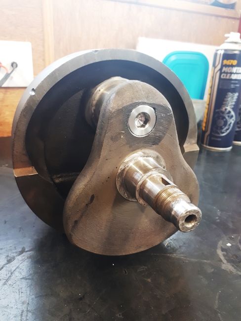
 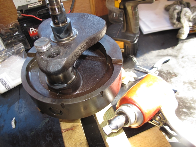 I was pleasantly surprised to find that the crankshaft journals were in excellent condition. There was very little wear showing on the bearing shells and no sign of any scoring on the crankshaft. I measured the journals with a micrometer and they were within the stated tolerance of 1.6235" - 1.6240" with no measurable ovality. That's good news as I won't need to get the crankshaft re-ground. I'll put a new set of "STD" shells in the new connecting rods and we'll be good to go. That just left one more job today... and one I wasn't looking forward to, removing the screw plug securing the sludge trap. I needn't have worried. Once again, having the right tool proved invaluable. There was just the original centre punch mark, showing that the plug had never been removed. That was relieved with a 3mm drill. You need heat first to break down any sealant that might have been used. Out came the oxy-acetylene torch. The plug was heated until it was smoking hot, then a 1/2" square drive screwdriver bit was used in the pneumatic impact gun. The plug just unscrewed... Lovely, no drama!!
Saturday, 12th March, 2022
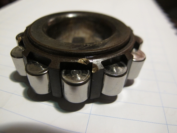
Ok... perhaps it didn't all go as well as I thought. When I had a closer look at the drive side main bearing inner race that I'd pulled off the crankshaft, I realised that it had sustained a little damage from the bearing puller that I'd used. As the bearing had felt perfect, I had intended to re-use it. Now, however, I'll have to replace it. The bearing still feels good, but it is highly stressed part, spinning at up to 6,500 r.p.m. Those tiny nicks in the roller cage are "stress risers" and I certainly don't want the cage to disintegrate at those revs.
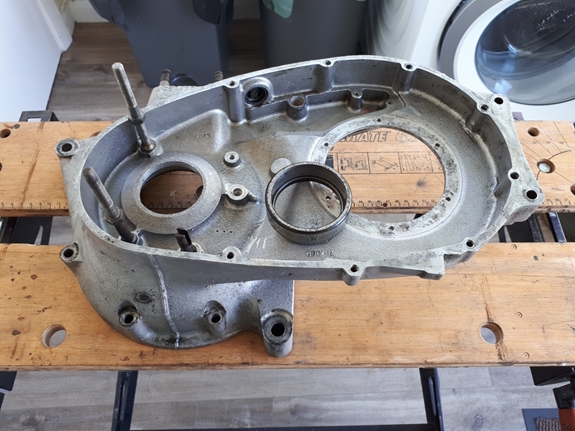
That meant that I now had to remove the bearing outer ring that was firmly located in the drive side crankcase. There was no way that I was able to use any form of extractor or puller so it was back to an "old school" method that had got me into serious trouble with my mother when I used it to remove a similar bearing from a 500cc Matchless crankcase when I was a teenager. Mum came home earlier that I'd expected and wasn't best pleased to find me "cooking" motorbike bits in her cherished oven!! Which was exactly what I had to do again now. The crankcase half was well brushed with "Gunk" and pressure washed to remove as much dirt and oil as possible. Then it was popped into my oven, set at 180°C for half an hour. The hot case was dropped face down onto a couple of wooden blocks on the kitchen floor and the bearing ring dropped out with a satisfying "ting". The old ways are sometimes the best!!
Tuesday, 15th March, 2022
 Messy job day, today. Namely cleaning out the sludge trap in the crankshaft. First I had to get the old tube out. That was fairly easy, using what is known as the "Hugh Mackie" method... Don't ask, I've no idea! It involves using a 5/8" x 11 t.p.i. taper tap to cut a few threads inside the tube, screwing in a suitable bolt and using that to extract the tube. I have a new tube to put back so the old one was discarded. Cleaning out meant just that... getting rid of 51 years worth of sludge. I used copious amounts of white spirit, various puggling implements and a bottle brush. In the end I was happy that is was clean and all the various oil ways were flushed out with brake cleaner. The new tube was inserted, making sure that the locating hole was lined up with the bolt that secures it. The bolt was cleaned and a drop of blue Loctite 242 was applied to the thread. That was tightened to the specified 33 lb/ft torque. (Just to be pedantic here... sorry, I used to be an engineer... The "pound-foot" (lb/ft) is the unit of torque. The angular force applied to an object by a one pound weight at a radius of one foot. The "foot-pound" (ft/lb) is a unit of work. The energy required to move a one pound weight a linear distance of one foot. Make sure you get it the right way around. Here endeth the lesson.)
With the tube securely located, that just left the screw plug. The subject of much debate.... to Loctite, or not to Loctite. From the factory, the plug was secured by staking with a centre punch. Conventional modern wisdom says that staking is BAD. It creates "stress risers" which could possibly lead to crankshaft failure. I've chosen not to physically stake the plug and applied a liberal coating of blue Loctite 242 to the plug and screwing it down with the pneumatic impact wrench. I did check beforehand that when fully home, the plug did not block, or partially block the oil feed drill way. Most important, that!
Monday, 28th March, 2022
This morning, I took the crankshaft, with the associated bits and pieces, down to Basset Down Balancing in Hungerford for them to work their magic. The gentleman I spoke to assures me that they will take great care of all the bits and return them to me, dynamically balanced, in due course. That should make for a very smooth running engine, or as good as a 360° parallel twin can be, anyway.
Thursday, 7th April, 2022
Right... new camshafts. I have always believed that Triumph spare parts manufactured by LF Harris, who actually manufactured Triumphs back in the 80's, were of high quality, being widely advertised as be made to the original manufacturer's drawings. Hmm... not so, it seems. A few says ago, in an idle moment, I offered up the timing gears to the new camshafts as I was curious as to whether the fit was any different to the old camshafts. The fit on the new exhaust cam was about the same as the old one. Not exactly a "push fit" but the two parts did go together using the Triumph assembly tool. The new inlet cam was a different matter. The two parts would not go together at all. In fact, I was in danger of stripping the thread on the assembly tool. I measured the diameter of both the old and the new inlet cams. The new one was 8 tenths of a thou (0.0008") bigger than the original. Now that doesn't sound like a lot, but it makes a huge difference to the "fit" of the two parts. I decided to measure the critical dimensions of all four camshafts and compare them to the sizes specified in the Triumph workshop manual. I was surprised, and disappointed, to find that the inlet cam was "out" on another critical dimension as well. The inboard (left hand) bearing journal was a massive 3 thousandth's of an inch undersize. The factory spec. is 0.8100" / 0.8105". The camshaft measured 0.8072" which puts it below the specified service limit before it's even in the engine. I will not be using that camshaft. Fortunately, the camshaft I took out measures ok on all the critical dimensions and the cam lobes are still in very good condition so that will be going back in with the new cam followers. The new exhaust camshaft, fortunately, was perfectly OK on all dimensions so that will replace the old one when the engine is reassembled.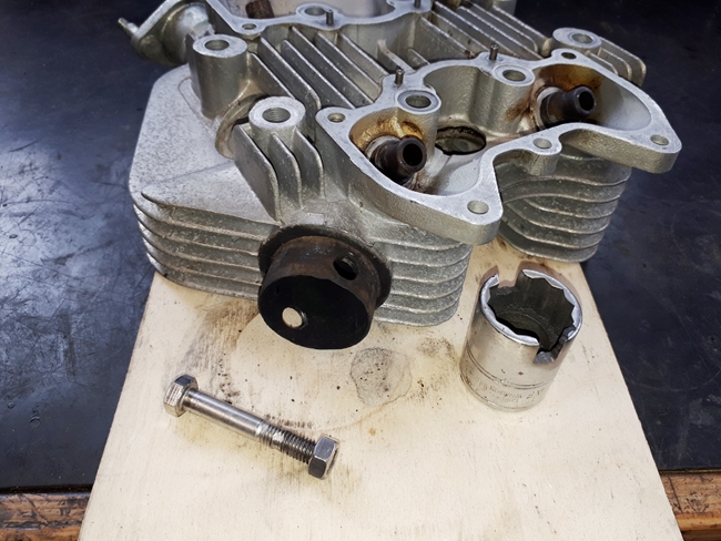
Next item on the agenda... the cylinder head, or more specifically, the exhaust stubs that screw into it. When I first rebuilt the bike, back in 2014, I remarked that the stubs weren't in very good condition but at that time, for one reason or another, I didn't replace them. This time I hope to do so, as they haven't improved any in the last 8 years. In fact, they've got worse. The left hand one in particular is very thin and ragged on the edge. Fortunately, that one unscrewed with relatively little difficulty and the thread in the cylinder head is still good and serviceable. The other one, however, has stubbornly refused to budge. Stopping short of physically destroying it in situ as I don't want to damage the cylinder head, I have admitted defeat. I've tried heat and I've even butchered an old socket so that I can use the impact wrench but to no avail. That leaves me with two choices as far as I can see. Leave it where it is and carry on using it. It is the better of the two and will probably be OK. Or I can drop the head into T & L Engineering. I spoke to them on the phone yesterday and they didn't seem particularly phased by the prospect. They said at the worst, they would machine it out, weld up the head and re-machine the thread. Do I really want to go down that road.... I'm not sure. I'll think on it some.
Friday, 22nd April, 2022
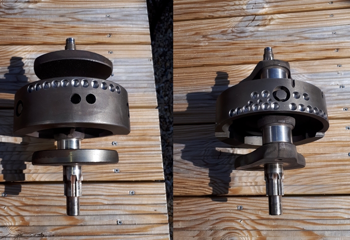
I've thought on it some, and I've decided that I'll leave the stubborn bugger where it is. Right... A few things have happened since my last blurb. I've collected the balanced crankshaft and associated bits from Basset Down Balancing and believe me, Swiss cheese doesn't come into the equation. There are a LOT of holes in the flywheel that weren't there when I left the crank with them.
 I guess it's time to start putting the engine back together. I've thoroughly cleaned the crankcase halves and installed a new main bearing outer ring into the drive side. This was pretty much the reverse of taking to old one out. Case into the oven at 180°C for 20 minutes and the bearing ring into the freezer. The ring dropped in with a satisfying "ting". A new ball race, circlip and oil seal were installed into the gearbox half for the output sprocket. The drive side main bearing rollers and inner ring were warmed up in the oven and installed onto the crankshaft's drive side axle.
Now comes the good bits... fitting the new "Thunder Engineering" connecting rods and with new bearing shells and bolting them up on the crankshaft. Sounds easy, doesn't it. Think again. The special big end bolts are made for Thunder Engineering by Austrian company Pankl Racing Systems AG and they were extremely tight. I had to clamp the rods to the bench and use a long breaker-bar to undo them. With the bolts out, I thought the bearing caps would come away from the rods easily. Wrong again. It took some very delicate persuasion to part them from the rods. Patience prevailed, however, and new rods and bearing shell were assembled to the crankshaft (using Permatex 81950 engine assembly lubricant) and the bolts tightened to 15 lbs/ft of torque before being finally torqued up to 42 lbs/ft. All fitted perfectly and the rods rotated around the crank journals smoothly without any sign of play. Goody goody!!
Monday, 25th April, 2022
To continue... The bottom end is now as complete as it's going to be whilst still in the engine stand on the bench. The crankshaft assembly is back in the crankcase and the two halves of the case bolted back together. That all went smoothly enough, and the crank spins without any sign of problems. I did wonder if the larger big end of the new con-rods would touch the inside of the crankcase but that appears not to be the case, fortunately. The camshafts were installed before assembling the crankcase as you can't fit them afterwards as you can on the Tiger 90. I've fitted the new exhaust cam but used the original inlet cam, as I deemed the new one unusable for the reasons mentioned above. The camshaft timing gears have been fitted to the camshafts, and the crankshaft pinion has also been installed. I've left the intermediate idler off for the moment. That will be put in place later when I set up the cam timing.
While the engine was on the bench, it seemed like a good idea to rebuild the gearbox. I'd already fitted the output gear through the new bearing and oil seal and the new larger 20 tooth final drive sprocket was fitted and secured with a new nut and locking tab washer. All the internal parts have been inspected and I found very little, if any, wear. The only parts I replaced were the two layshaft thrust washers. With a little judicious fiddling, the gear indexing cam-plate was fitted although at one point, I thought I might have to take the output gear out again. Fortunately, I didn't have to.
I've never rebuilt a Bonneville gearbox before so I had a look in the workshop manual for a little guidance. They recommend that the whole gear cluster assembly, including selector forks, are built up onto the mainshaft and layshaft then the whole lot offered up and fitted into the case. Yeah, right!! That would only work if you're a midget with three hands! Keeping the gears and selector forks in place whilst attempting to locate the mainshaft and layshaft into their respecting bearings proved frustratingly difficult. I struggled for the best part of an hour before deciding it was impossible. So much for looking in the manual. One of Robert Heinlein's "waldos" would have been really useful!! [Google it, if you don't know.] I went off in search of coffee and inspiration.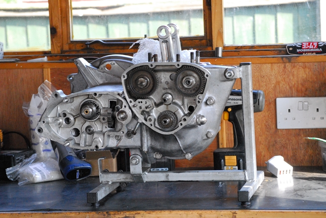
Building up a Burman gearbox is, by comparison, easy and straightforward. The mainshaft and layshaft are installed first and the various gears and selectors added, in sequence, until they are all in place. I wondered if I could build up the Triumph gearbox in a similar manner. Looking at the various components, I decided not, as there was a gear fixed on the mainshaft that would prevent it. I might just manage a variation of the method, though. I fitted the layshaft and the three innermost layshaft gears into the case. I left the large outermost gear, which spins freely on the end of the layshaft, off for the moment. Then fitted the selector fork and located the selector fork into the cam-plate. So far, so good. I balanced the two mainshaft middle gears and their selector fork on top of the corresponding layshaft gears. I carefully located the selector fork into the track on the cam plate and locked the two selector forks in place by pushing the selector fork rod through them and into the hole at the back of the case. I breathed a sigh of relief when it all stayed put. Carefully, I threaded the mainshaft through the gears that I'd just put in place, and finally, put the last gear onto the layshaft... Yes!!....Job done.
All I had to do now was fit the gearbox inner cover, ensuring that the cam-plate and the cam-plate operating quadrant were correctly indexed. That actually took two attempts before I got it right and could select all four gears and neutral in their correct order. Finally, the kickstart ratchet plate, pinion and spring were all secured with the nut and a new tab washer. That nut working loose caused the bike to break down a few years ago so I added a little blue Loctite as extra insurance.
Wednesday, 27th April, 2022
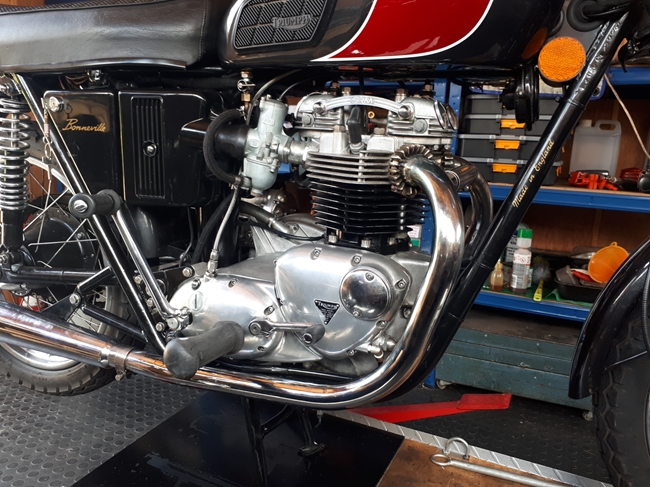
All was now pretty much ready for the engine to go back into the frame. I've deliberately not assembled the barrel and pistons onto the crankcase for a reason that I'll come to later. I have, however, assembled the cam follower guide blocks into the new barrel and dropped it onto the case just to make sure that there's no problem with the base studs and dowels. Happily, all was ok and the barrel fit was good. With the rolling chassis up on the bench after having been de-greased and pressure washed, it was a relatively simple task to take the engine off the work stand and drop it into the frame. Just two studs locate the engine, a long one at the bottom and a shorter one at the front. There are two spacers on each of these studs and it's important that they are fitted correctly, the longer one of each pair on the right hand side of the engine. They were only done up "finger tight" at this stage. The triangular rear engine plates were fitted and all the studs and bolts fully tightened. 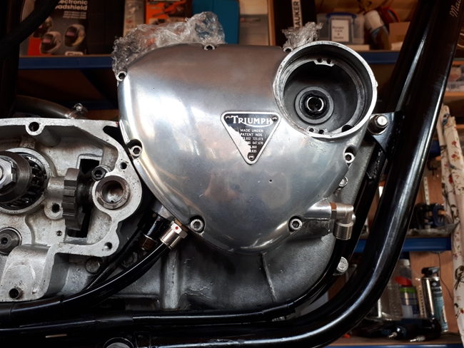
If you've read "Part 1" of this saga, then you'll no doubt remember that the lubrication system on this engine isn't exactly as it left the Meriden works. I've fitted a replaceable canister oil filter. Not that unusual, one might say, a lot of owners fit external oil filters. Indeed they do but most take the easy option and fit them in the oil RETURN line. My timing cover has been modified by a guy named Kirby Rowbotham in such a way that it re-directs the oil from the feed pump to the oil filter and from there, it is fed back into the engine via the oil pressure switch port in the front of the timing cover. That way, the clean filtered oil is fed into the engine, not back to the tank. A much nicer way of doing things. There is a drawback, however. You must ensure that the external oil lines and filter cartridge are completely filled with oil before starting the engine for the first time, or it may be starved of oil until the lines and filter have been filled. So... new oil filter, full of oil, screwed into place. The braided hoses from the frame tank to the engine have been installed but for the moment, the manifold block that bolts to the engine has a new gasket but is only finger tight. 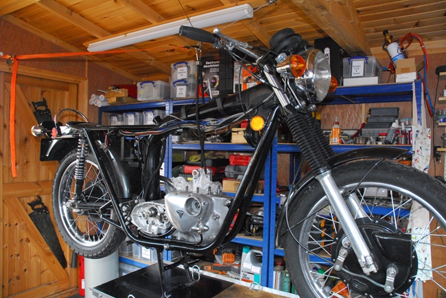 I've cut new lengths of nylon tube and fitted them to the filter housing. The oil tank has been filled with fresh Duckhams SAE40 oil (as recommended by Morgo for running in the new bores and pistons). When oil started seeping from the manifold block, the feed hose was full and I fully tightened the retaining nut. Now I had to turn the engine over by hand to prime the oil pump. The conrods were supported by a rubber bungee cord to keep them from knocking on the crankcase while I was turning the engine over. After a few rotations, oil was being pumped out of the nylon tube fitting at the rear of the timing cover. The pump was primed so the nylon tube from the engine to the filter was connected. It took quite a few more turns of the engine before both nylon tubes and the filter housing were purged of air and oil was coming out of the nylon tube that comes from the filter. That was then connected to the fitting at the front of the timing cover. So far, so good... I turned the engine over another dozen or so times to ensure that the oil passage in the timing cover was full and oil was being pumped into the crankshaft. I'm fairly confident now that the whole lot won't seize up when I start it for the first time.
Thursday, 5th May, 2022
 I have discovered a problem!! Whilst cleaning the rear wheel rim, I found an unacceptable amount of play in the rear wheel bearings. The wheel came out for investigation and I found that the bearing retaining ring on the brake drum side had worked loose, allowing the ball bearing on that side to move about in the hub. This has caused some wear to take place and the bearing is no longer a press fit in the hub... more like a drop-in fit! I estimate that there is probably 2 or 3 thou' radial clearance between the bearing and the hub. I've bought a pair of new bearings and as a "temporary measure" until I can source a replacement hub, I'll put the new bearing back on the brake drum side with a little "Loctite 609" and make sure the retaining ring is done up tightly and securely. Hopefully, that will do the trick in the short term. Meanwhile, back in the engine department, the primary drive has been re-instated.
Wednesday, 18th May, 2022
Real life has got in the way of things a bit just recently and I've not got as much done as I'd hoped. Having sorted out the lubrication system I could put the gearbox outer cover back on... but not before I'd connected up, and bled, the hydraulic line for the clutch slave cylinder. The DOT4 fluid had been in the system for at least a couple of years so I flushed it all through with new fluid. That accomplished, the gearbox outer cover was put back with a new gasket. Now I could set up the clutch.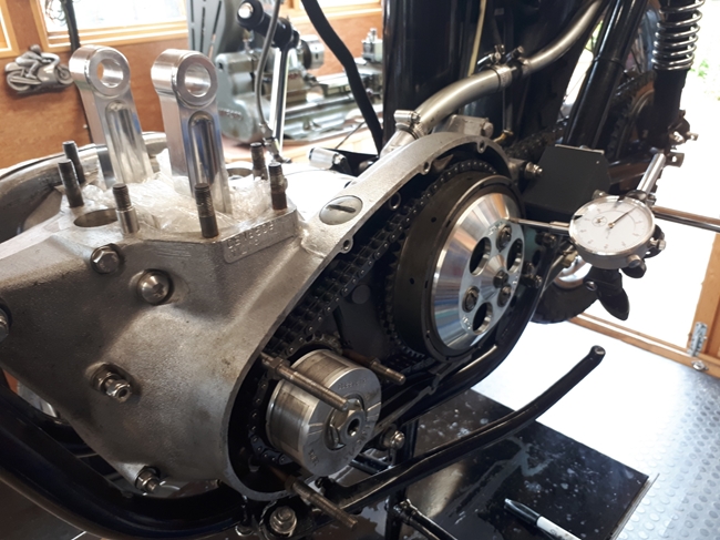 The clutch hub and drum, I installed when I re-instated the primary drive a few days ago. I just needed to put back the clutch pushrod and the plates. I tightened the clutch spring nuts until the end of the studs was approximately flush with the bottom of the screwdriver slot. The clutch was operated a couple of times to ensure the plates were all ok. Now it just needed adjusting. The adjuster locknut in the pressure plate was undone and the adjusting screw done up until it just started to lift the pressure plate. Then it was backed out 1/2 a turn and the locknut re-tightened. Now I set up a dial test indicator (DTI) on the edge of the pressure plate. The spring retaining nuts were adjusted until the plate lifted evenly all the way around when the clutch lever was operated.
The clutch lever / master cylinder is an AP Racing item with an adjustable ratio delivery. It could be set, at one end of it's range, to not lift the pressure plate at all. At the other end, it would lift the pressure plate about 0.150". It is, however, a compromise... a balance, if you like... The greater the lift, the greater the effort needed to operate the lever. I've set it up to lift the pressure plate 0.080". That ensures that the plates will separate when the lever is operated and that the effort required to operate the lever is not too excessive. A bit fiddly and time consuming to set up, but worth the effort.
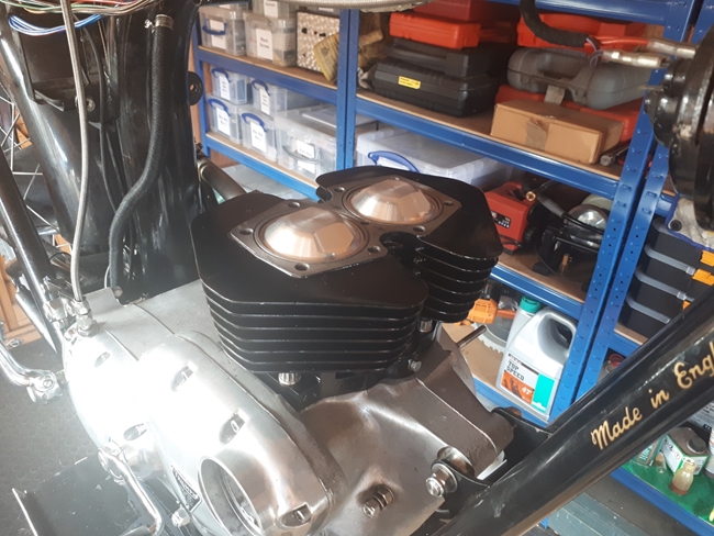 Logically, the next step is to fit the new pistons and barrel. I'd already checked the fit of the gudgeon pin supplied with the new pistons into the little end of the new Thunder Engineering con-rods. It was perfect. So... I could fit the pistons to the rods and lower the barrel over them, compressing the piston rings as I went or do it the other way. I did it the other way. I fitted the gudgeon pin circlips into their grooves in the pistons on what would be the inside end of the pins. The gudgeon pins were slid out the pistons in the other direction. The pistons could then be easily inserted into the bottom of cylinder bore, up to the gudgeon pins. Now I had to hold the whole assembly over the crankcase, locate the con-rods in the pistons and push the gudgeon pins through the little end of the con-rods. It's easier to say than to achieve but with a little ingenuity it's not difficult. I supported the cylinder barrel under the top frame tube with a length of "para-cord" while I fitted the gudgeon pins. With the pins in place, the remaining circlips could be fitted to the pistons, taking very good care not to drop them into the crankcase!! That done, the cylinder was lowered onto the crankcase (I'd remembered to position the new cylinder base gasket before I started) and secured with the special, 12 point, nuts. The last job today was to put the valves back into the cylinder head and refit the springs.
Thursday, 19th May, 2022
Today, my only task was to finish off the top end. Fitting the cylinder head is fairly straightforward if you do it correctly. The secret to an oil-tight assembly is the amount of "crush" you get on the seals at the base of the pushrod tubes. This only applies to later engines that have the "wedding bands" at the base of the tube to constrain the square section seal. You should aim for 0.035". In a good gasket set you should get 4 red "O" rings, all the same size, and 4 translucent square section seals, two thicker ones and two thinner ones. The standard copper head gasket is 0.040" thick. I also had one of 0.060" and one of 0.080" from different past rebuilds.
Fit one of the thicker square seals over each of the tappet guide blocks, and drop on the "wedding bands". If there are old "O" rings fitted into the grooves at the bottom of the push rod tunnels, remove them. Position the pushrod tunnels onto the tappet guide blocks. Lubricate two of the red "O" rings and fit them into the recesses in the underside of the cylinder head. Put the copper head gasket in place and fit the cylinder head onto the push rod tunnels, being careful not to damage the "O" rings. Push it down with you hand to ensure everything is firmly seated. Now the important bit... measure the gap between the gasket and the cylinder head with (ideally) two sets of feeler gauges... one set in each side to keep the head level. As stated earlier, the ideal gap should be 35 thou'. If necessary, change the square seals for thinner ones. Once the gap is as close as you can get it, reassemble with the second lubricated red "O" ring fitted to the bottom of the pushrod tunnels. You may need to put the rear two centre bolts into the head before fitting as getting them past the frame top tube can be problematic! The 8 large bolts should be torqued to 18 lbs/ft and the small centre bolt to 15 lbs/ft.
The pushrods and rocker boxes were installed with new "Cov-Seal" gaskets, imported from "The Bonneville Shop" in the USA. That just left the valve clearances to be set... 2 thou' inlet and 4 thou' exhaust.
Tuesday, 24th May, 2022
I made an executive decision a couple of days ago and re-fitted the Pazon ignition system. While the PowerArc ignition is undoubtedly the better system, it would mean a lot of re-wiring to fit it. The Pazon system has been working faultlessly so on balance, I wouldn't be gaining much for a fair amount of work. Right... I've acquired another rear wheel hub. It looks to be in pretty much perfect condition... almost new old stock. It has the original factory silver paint and original un-shielded bearings (but no retaining screw rings). There is even paint in the spoke holes and they look like there has never been a spoke in them. The brake drum lining is also perfect with absolutely no wear showing. I'll put that away somewhere safe (where the workshop "pixies" can't get at it) and if my Loctite "fix" of the current rear hub fails, then I have one to replace it.
Thursday, 26th May, 2022
 The rest of the bits have been bolted back and the bike is ready to go. I put a gallon of premium petrol in the tank, tickled the carbs and kicked her over a couple of times with the ignition off. Ignition on, one kick and away she went... what a little beauty!! It took a worrying few seconds before the gauge started to show a rise in oil pressure, which settled out at 65 p.s.i. which was perfect. As there seemed to be no issues, another gallon was put into the tank and I took her out for a short(ish) 20 mile shake-down run.
The extra torque from the engine was noticeable and the exhaust had a more pronounced bark to it but it wasn't obtrusive. I kept the revs down to under 3000 for the most part with just a couple of very brief bursts up to 4000. When I got back I noticed that there was some oil behind the engine, on top of the gearbox. It appeared to be coming from inlet rocker box or rocker box inspection caps. I'll need to take the tank off again to sort that out. The bike is back in the workshop for that issue to be sorted. All in all, I am very happy with the result. The engine seems to run smoothly but it won't be until I can spin the engine up to 5 or 6 thousand r.p.m. to see if the dynamic balancing has had the desired effect.
Friday, 27th May, 2022
This morning, I took the tank and seat off. The carbs had to come off as well to give me better access. To be honest, I couldn't see exactly where the oil was coming from but it was obviously coming from somewhere at the top, rear of the engine. I'm fairly sure that it wasn't coming from the rocker box gasket as there was oil on the outside of the engine above that and those Cov-Seal gaskets are the best. I managed to get a little movement on the rocker box securing nuts and bolts. That only left a couple of places that, realistically, the oil could have come from. I checked the rocker oil feed pipe and manifold. The acorn nuts were tight and the copper sealing washers had been annealed before assembly so that was eliminated. The braided flexible pipe was dry so that hadn't been the leak either. That just left the new rocker inspection caps that I'd fitted or the feeler gauge access plugs in the sides of the rocker box.
I unscrewed all four items. The new rocker caps seemed tight enough but possibly the red fibre washers weren't sealing as well as they should. They are very hard. I cleaned the threads with brake cleaner and applied a smear of "ThreeBond 1184" grey sealant before screwing them back as tight as I could. The feeler gauge access plugs, I've decided to replace. The threads appear to have been eroded (or corroded) away in places, so I've ordered replacements. When they arrive, I'll put those back with ThreeBond as well.
Wednesday, 1st June, 2022
 The best laid plans blah, blah, blah. It would appear that I have to dismantle the top end again. Another run out shows that I still have two leaks to sort out. There is oil seeping out from under the cylinder barrel. I used a new gasket and the 8 nuts have been fully tightened. I didn't think that it would be necessary to use gasket sealer. It seems that I was wrong... ho hum!!
Despite what I said earlier, it seems that oil has been leaking out of the pipe that takes oil to the rockers. I will now replace all the oil lines as a matter of course. I have a set of stainless steel single ear crimp hose clamps that I will use instead of the screw pipe clips that I have on there now. So... "Daisy" is back in the workshop for an indeterminate period of time. Hopefully, when she comes out again, she will be oil-tight.
Wednesday, 22nd June, 2022
Whilst Daisy was in the workshop, things took a turn for the worse. I noticed that there were some oil drips under the bike that were coming from two different places. Green Duckhams SAE 40 was dripping, albeit slowly, from the crankcase joint and brown gearbox oil was leaking from the joint between the crankcase and the gearbox inner cover. These two locations have one thing in common.... I'd used Loctite 518 as the sealing medium and it appears that it doesn't live up to the advertising blurb!! So... I had no alternative other than to take the engine out of the frame again, completely dismantle it and start again. This time I used the sealant that I should have used in the first place.... ThreeBond 1184. So, the engine has been stripped, cleaned, reassembled and put back in the frame. All oil has been replaced and so far, the engine is completely oil-tight. The final test will be when I take it out for a run again. Unfortunately, life sometimes gets in the way and the test ride will have to wait for a while.
Sunday, 3rd July, 2022
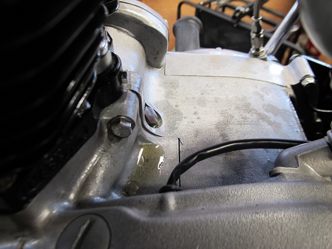
Things have not gone to plan... Bummer. I took the bike out for a test run a couple of days ago and whilst there were no drips of oil from the crankcase joint or gearbox, there was STILL and annoying little puddle of oil sitting on top of the crankcase behind the cylinder, as per the photo above. Having replaced the cylinder base gasket and used a smear of blue Hylomar on both sides, I'm pretty confident that it's not the base gasket that's leaking. I used another set of o-rings and silicone seals on the pushrod tubes and selected them to give the recommended 35 thou of "crush", so I'm equally sure that the oil is not coming from there.  That only leaves one place that the oil can be coming from and that's from the crankcase itself. All of the cylinder base studs, with the exception of the two studs on the left, nearest the primary drive, are screwed into blind holes. The two nearest the primary drive are not. The holes for these are drilled right through into the inside of the crankcase, and it is not unknown for oil to work its way up the threads and out from under the nuts.
So... With that in mind, yesterday I removed the nuts on the two studs that were above the oil leak and cleaned the studs and cylinder holes with brake cleaner. I applied some ThreeBond to the threads, and put a copper washer under two new nuts, which were then tightened as hard as I could with a short(ish) ring spanner.
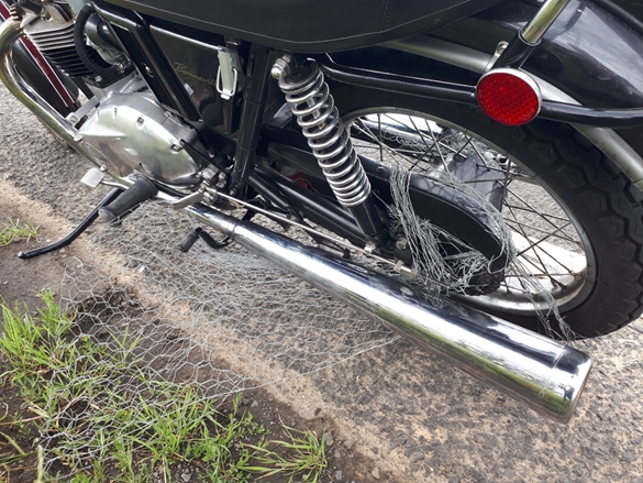
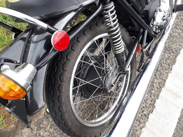
Today, I set out on yet another test ride. After 40 miles and just a couple of miles from home, disaster struck. I ran over a great lump of chicken wire mesh in the middle of the carriageway on a fast stretch of the A17. It trapped my left foot to the footrest and wrapped itself around both sides of the rear wheel, jamming it solid. I skidded to a halt at the side of the road. There was no way I was going to get it untangled without some serious wire cutters, which I didn't happen to have with me, so I phone my insurance breakdown cover people. 40 minutes later, Daisy was on the back of one of Tears breakdown lorries. The flailing wire mesh had wiped off the rear light and the number plate, put some deep scratches in the rear mudguard and made a mess of the final drive chain guard. All very annoying but in the great scheme of things, not catastrophic.
Oh, yes... I'm happy to say that there was no sign of any oil on top of the crankcase, so I seem to have sorted that!! Win some, loose some.
Tuesday, 5th July, 2022
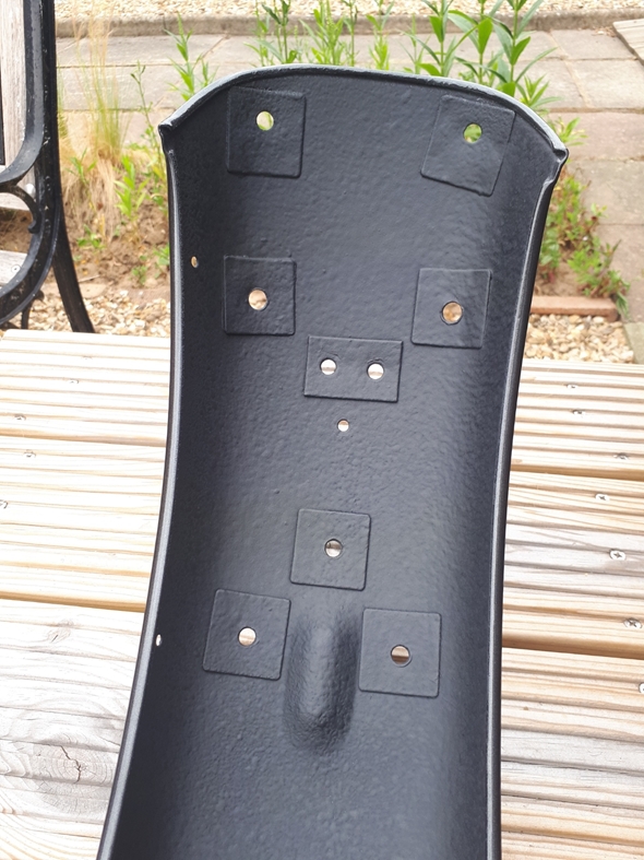
Ok, then.... Daisy is back in the workshop and the rear end has been disassembled. It took a little "teasing" to get rid of all the wire mesh that was wrapped around the rear wheel but apart from the speedo gearbox and pulse sender, the wheel was relatively un-damaged.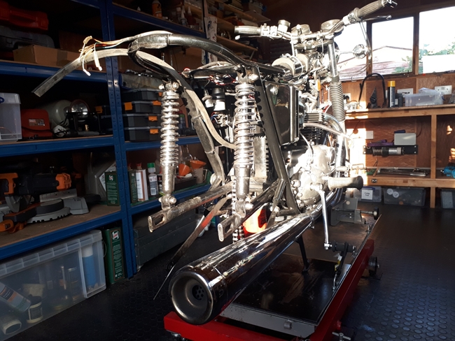 The rear mudguard needs repainting, and a number of other parts need attention from my friendly powder coating company. I also need to buy a few new bits. A speedometer drive gearbox and pulse sender unit for the speedometer were damaged badly enough to warrant replacing, as was the rear chain guard. That was seriously bent! The rear light carrier that bolts onto the mudguard was a bit battered but a little work with a small hammer and it's as good as it ever was. It will need powder coating, though. The same applies to the grab rail loop. It didn't get bent, but it did suffer some deep scratches. A new rear light assembly and a new number plate have been ordered. The two steel brackets that the number plate attaches to have been straightened but will need to be powder coated. I've also ordered a new final drive chain as the one fitted has been on there since I rebuilt the bike 7 years ago and was showing signs of wear. A brand new rear chain guard, made by L.F.Harris, is also on it's way. There's not much I can do until the paint work and powder coating have been done, so I guess the bike will be in the workshop for some time to come. Ho hum...
Wednesday, 6th July, 2022
I had a thought this morning... stop sniggering at the back, there... regarding the painting of the rear mudguard. My initial thought was to take it over to Dream Machine, in Nottingham, as they made a very good job of the tank when they repainted it last September. Then I started to weigh up the cost. DM are good but they aren't cheap, the tank cost me close to £450. I can't see them doing the rear mudguard for less than £300. Add to that the return trip to Nottingham, twice, and the cost starts to mount up. 340 miles at 45 miles to the gallon equates to roughly 7.5 gallons of diesel. That's about 35 litres and at the current price of £2 a litre, that adds £70 to to cost of the paint job. That's going to make it a very expensive rear mudguard.
Within walking distance of where I live is The Lutton Bodyshop. I've never dealt with them before, but it has to be an option, so I gave them a call. Yes... they do a lot of motorcycle paint work, particularly for the local Harley Davidson fraternity. To cut a long story a little shorter, I took the mudguard round to them, met the main man, Kristian Vere, who's now going to repaint the mudguard. Cost, around £200. That would be a considerable saving on what it would cost me to take it to Dream Machine. Could be a result!!
Saturday, 23rd July, 2022
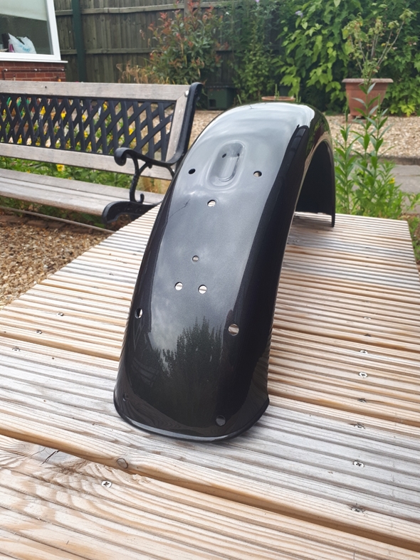
 Yesterday morning I received a call from Jack Vere (Kristian's son) at The Lutton Bodyshop to say that the rear mudguard was ready for collection. I went round to collect it a little later that morning and I have to say that I'm impressed. They've made a cracking job of it. The finish is superb and the colour match was excellent. They've even painted the inside with stone chip protection paint. The cost was as estimated, two hundred of our finest British Quids. That was the first job that they've done for me but I suspect that it won't be the last.
A few days ago I took the remaining parts that needed powder coating down to Richard Burns at Breckland Finishing. Hopefully they wont be too long and I can start re-assembling Daisy's rear end!!
Tuesday, 17th August, 2022.
I've collected the powder coated parts from Breckland Finishing and the back end of the bike has been rebuilt. It all went together remarkably easily. The only problem I had was with the new pulse unit for the electronic speedometer. The old one was a two wire sensor. The new one has three wires. I connected it up as per the instruction sheet supplied and spun it with the electric drill. Nothing... the speedometer needle didn't even flicker. Not good news. Digital Speedos, who supplied the new sensor, weren't a great deal of help. All they would say was that they had supplied them in the past with no problems. I have some knowledge of various sensors and it seemed likely that the two wire sensor would need a "pull-up" or "pull-down" connection to make it work, whilst the 3 wire sensor with connections to both +ve & -ve sides of the electrical system wouldn't. The only wire from the speedometer that looked a likely candidate was the red wire that was connected to the -ve from the ignition switch. I took a chance and disconnected it. Voilà... the speedo now registered when I used the drill to spin the sensor. That was a result!! All that remains to do now is replace the tank and seat, but that will have to wait as I'm going away for few days for a folk festival.
Thursday, 25th August, 2022.
My joy was short lived... Having got it all together and with the bike running in 1st gear on the bench, the speedo again refused to even flicker. It seems a little more work was needed. 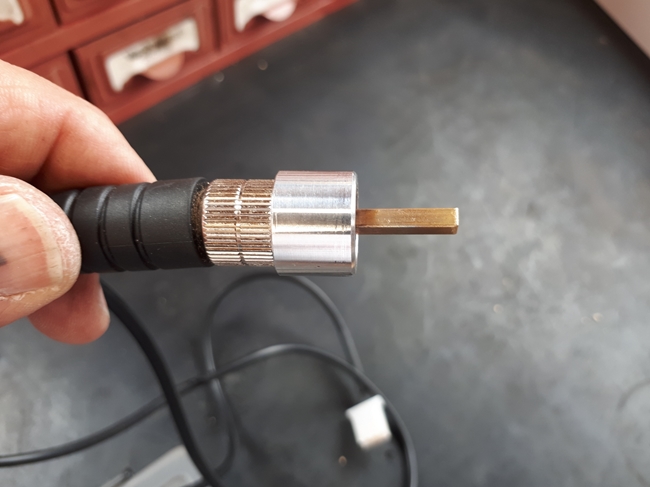 The threaded collar on the new sensor has a different thread to the speedo drive gearbox so Digital Speedos had supplied an adaptor to go between the sensor and the drive gearbox but that meant that the little square peg in the sensor was no longer long enough to engage in the square hole in the drive gearbox, so it wasn't being rotated when the wheel went round. Also... it wasn't big enough. The hole on the gearbox was designed to fit a speedometer drive cable. That has a square section formed on the end that is 1/8" square. The peg in the sensor was slightly less than 3mm square. Digital Speedos had attempted to correct this by using a piece of heat shrink tube to increase the size but that kept sliding off. Then I had a bit of a very uncharacteristic brain wave. A long time ago, in a different life, I built and raced model slot cars... Scalextric on steroids. A root around in the loft produced my old modelling kit and no, my memory hadn't failed me, I still had some of the small section brass tube that I used to build car chassis with. It turned out to be perfect... 1/8" square on the outside and with a tiny bit of filing, fitted over the sensor peg. A short length, long enough to engage with the gearbox, was secured to the sensor peg with a dab of Loctite 638. With everything back together again, the speedo was quite happily indicating when I spun the rear wheel. My joy has returned.
Monday, 26th September, 2022.
A few days after my last blog entry, I took Daisy for a run down to my favourite pub, The Strathmore Arms, in St. Paul's Walden. As she only had around 100 miles on the clock, I kept the revs and speed down to a modest 60-70 mph. There were no issues with the engine what-so-ever. She pulled strongly from low revs and seemed willing to rev. The oil pressure was a constant 70 psi when the engine was turning over in excess of 2000 rpm. At tick-over, that dropped to a very acceptable 30 psi. So far, so good. The engine and gearbox had remained totally oil-tight... hooray!!
There was, however, a problem!! Do you remember, back in May, that I discovered some play in the rear wheel bearings? Well, that play was back again. It seems that my "temporary" fix with Loctite 609 was a lot more temporary that I'd hoped for. At some point in the future, the replacement hub will have to be powder coated and the stainless steel rim and spokes, currently on the worn hub, will have to be re-laced onto the new one. That, however, will have to wait as the workshop is currently occupied by Lilly, my Tiger 90. Her timing side main bearing bush has failed and the engine is being re-built... Ho hum!!
Friday, 3rd February, 2023.
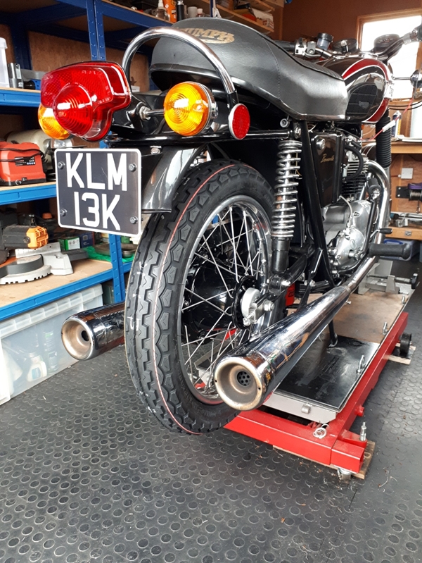 I'm happy to say that Daisy is now back to her best. A few weeks ago I wheeled her into the workshop and took the rear wheel out. The tyre, tube and rim tape were removed and disposed of in the approved manner. I dismantled the wheel as the rim and spokes would be re-used. The replacement hub that I acquired was checked over again and with the rim and spokes, was taken over to CWC at Coleshill. They media blasted, masked and powder coated the hub gloss black and rebuilt the wheel using the rim and spokes that I took from the old wheel. They also fitted a new Dunlop TT100 tyre, tube and rim tape. Yesterday I collected it and passed over a significant wad of dosh. This morning, I installed new bearings and associated bits, then put the wheel back where it belonged. It was a nice, early spring day so a quick blast around my test circuit was called for, just to make sure everything was ok. I'm pleased to say that it was. The rebuilt engine feels strong and sounds great. There are no signs of any oil leaks. Another run down to the Strathmore Arms will see the 500 mile running in period complete so I'll drain the SAE40 oil out and replace it with the usual 20w50, along with a new filter.
Here ends Part 2. If anything else significant needs to be documented, I'll start a new chapter, Part 3, and put a link here so that you can find it, should you so wish. Thank you come coming this far.
Well... things never go exactly to plan when you're dealing with old Brit Iron that seems intent on causing problems, so "Part 3" can be found HERE.
Link to Index and Home Page.
Link to Triumph T120R - Part 1.
Link to Triumph Tiger 90 page.
Link to AJS M18S page.
Link to Matchless G3/LS page.
Link to Matchless G80CS page.
Link to Honda VFR750 page.
Link to Norton 650SS page.
Last updated 03/02/2023.